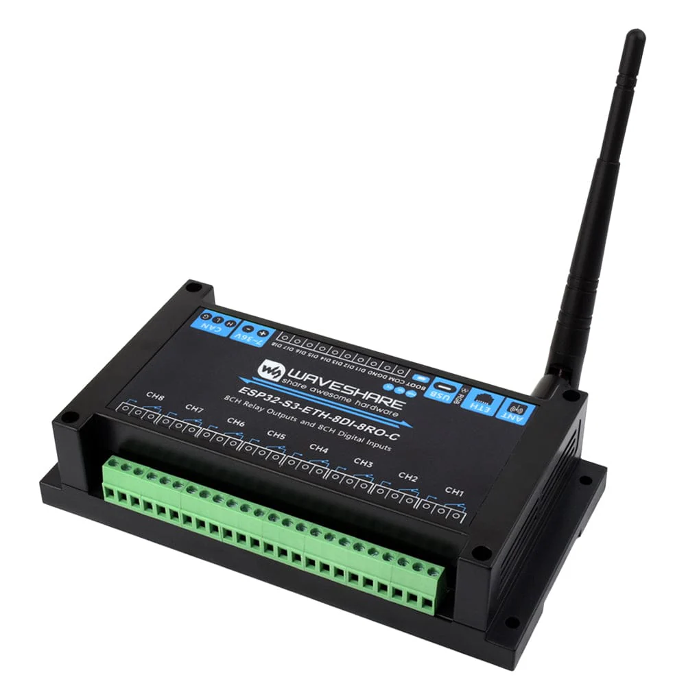
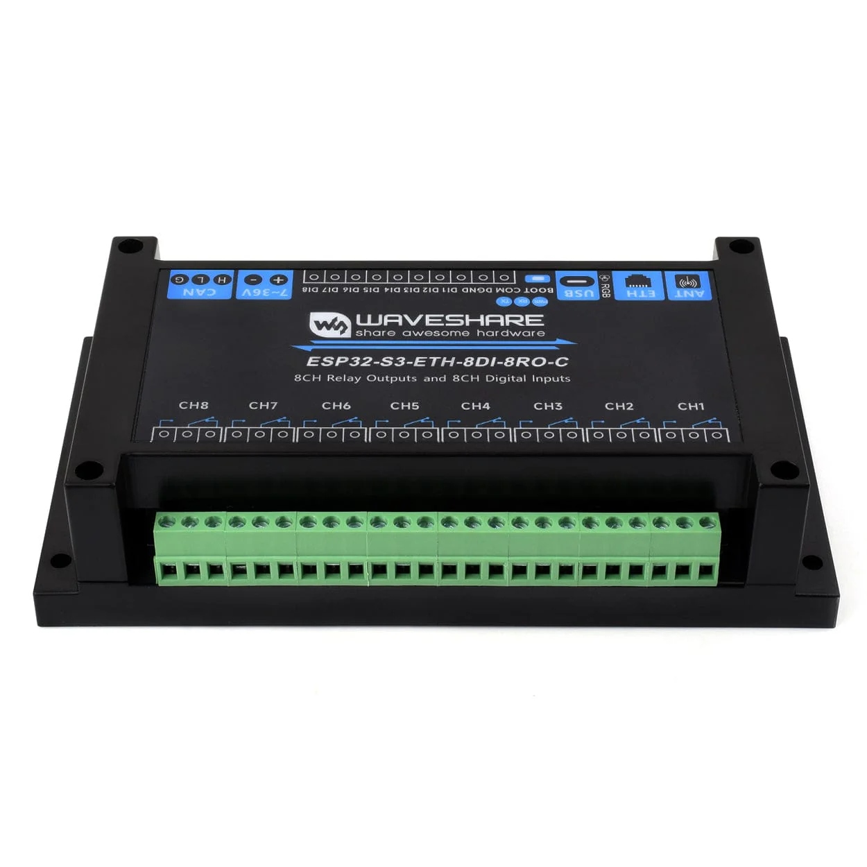
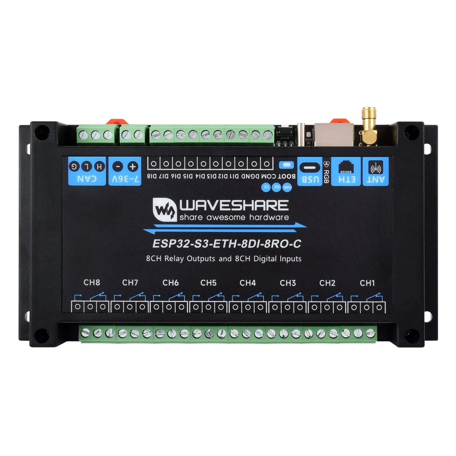
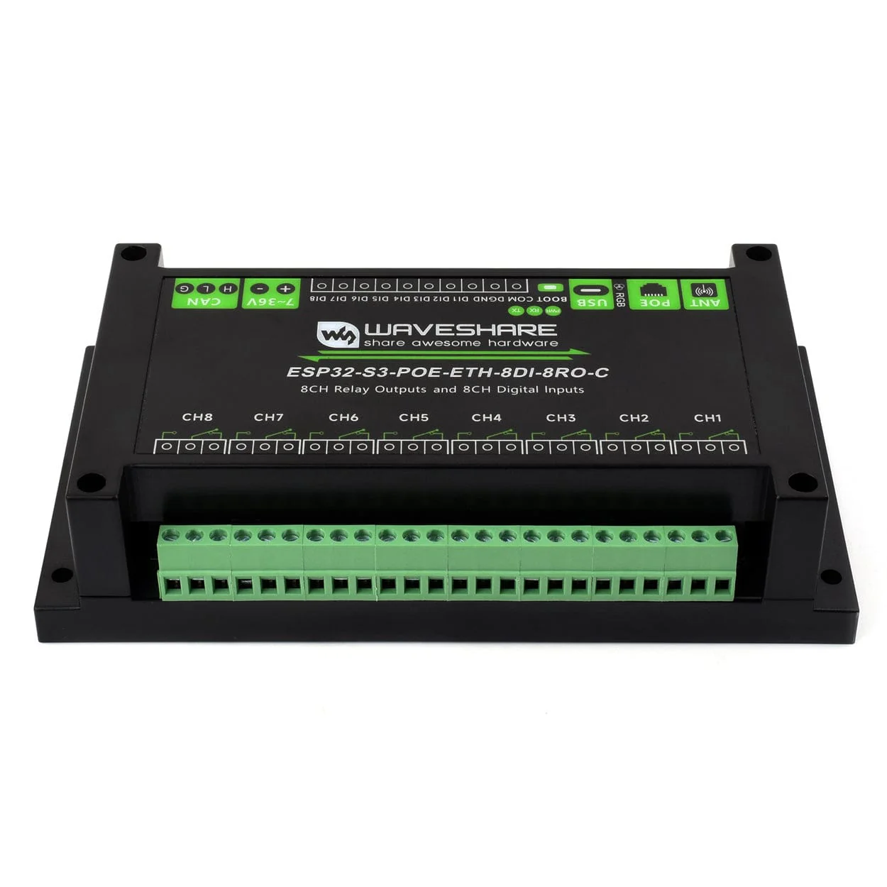
8-Channel ESP32-S3 Wi-Fi Relay Module with CAN Interface
The Waveshare 8-Channel ESP32-S3 Wi-Fi Relay Module is based on an ESP32‑S3 microcontroller with an Xtensa 32‑bit LX7 dual‑core processor running up to 240 MHz, featuring 2.4 GHz Wi‑Fi and Bluetooth LE dual‑mode wireless, and adds a W5500 Ethernet chip over SPI for a 10/100 Mbps network port (with the option for PoE support).
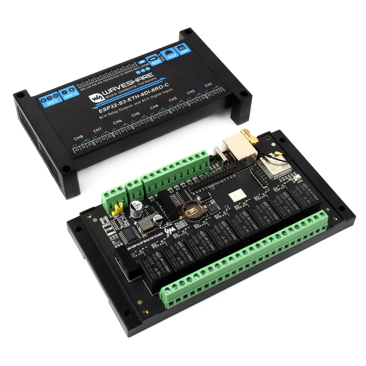
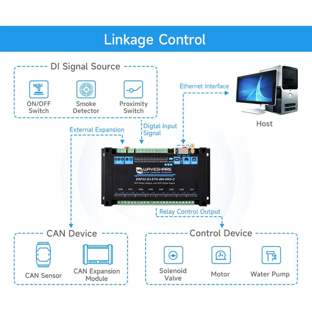
I/O is set up for real‑world control: high‑quality relays (≤10 A at 250V AC / 30V DC), passive and active digital inputs with bi‑directional optocoupler isolation, and linkage so relays can follow digital inputs.
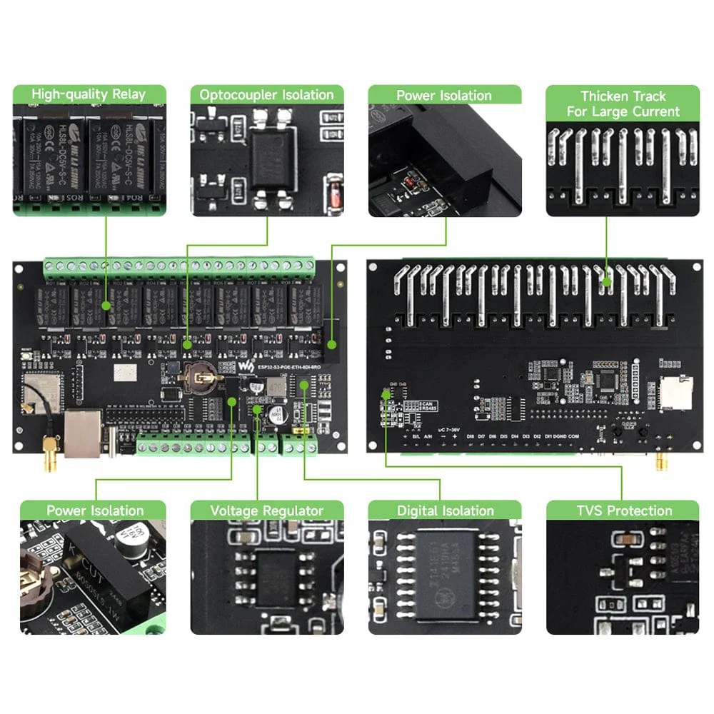
Optocouplers prevent interference from external high‑voltage circuits on the relay side, with digital isolation to keep external signals clean, and a unibody isolated power supply that provides a stable isolated voltage so the isolated terminal needs no extra supply.
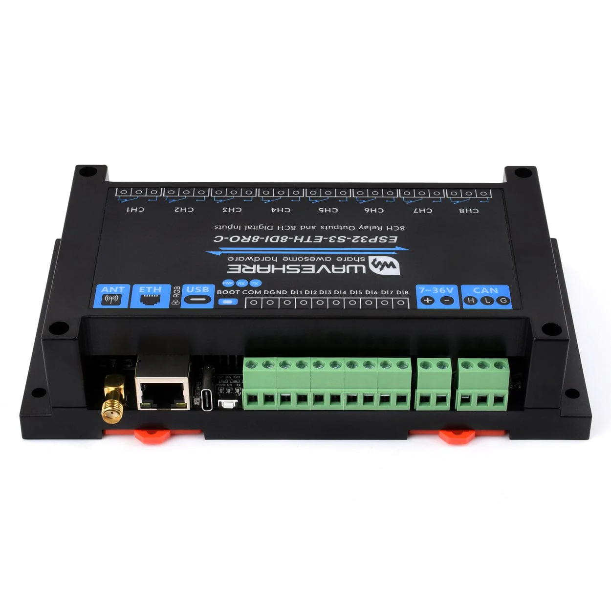
An onboard isolated CAN interface connects to a range of CAN devices, and a pin header gives access to other peripherals. Power it via the USB‑C port (also used for firmware downloading and debugging) or the screw terminal with a wide 7–36 V input.
An onboard RTC supports scheduled tasks (with a CR1220 battery holder for rechargeable coin cells only), there’s a MicroSD card slot for storing images and files, and you get a built‑in buzzer, RGB LED, plus power and CAN TX/RX indicators to monitor device status. It’s all housed in a rail‑mounted ABS case that’s easy to install and safe to use.
There are two versions of this product available - one with a standard/common Ethernet port, and one with a PoE network port (via a built‑in IEEE 802.3af‑compliant module), please select an option before adding to your cart.
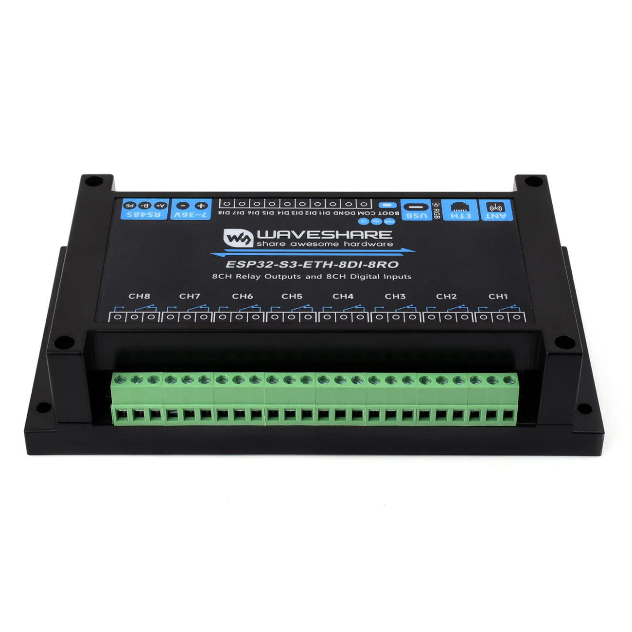
What's Onboard?

-
ESP32-S3-WROOM-1U-N16R8
- ESP32‑S3 series with Xtensa 32‑bit LX7 dual‑core processor, 16 MB Flash and 8 MB PSRAM.
-
8‑channel relays
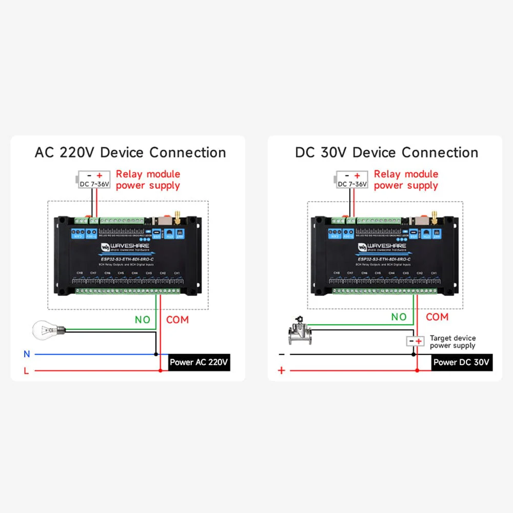
- Contact rating per channel: ≤10 A at 250 V AC or 30 V DC.
-
Optocoupler isolation
- Prevents interference from external high‑voltage circuits connected to the relay.
- Reset button
-
PoE header
- Connects to a PoE module to add PoE capability (PoE‑port version only).
- Boot button
- Power IC
-
Digital isolation
- Prevents interference from external signals.
-
Power‑supply isolation
- Provides a stable isolated voltage; no extra power supply needed for the isolated terminal.
- Bi‑directional optocoupler isolation
-
RTC battery holder
- CR1220 size, supports only rechargeable 3.0–3.3 V batteries.
- Buzzer
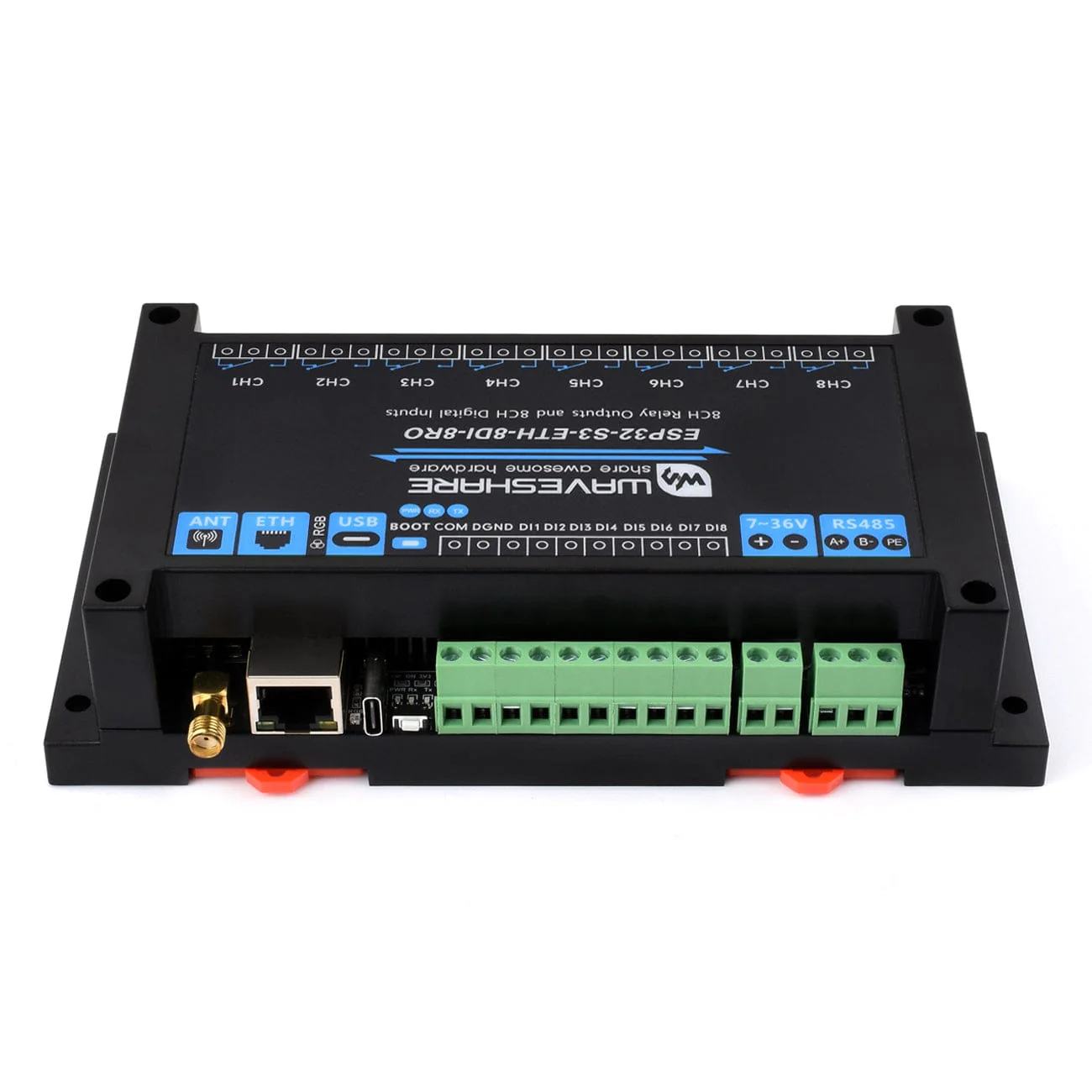
- Digital input screw terminals
-
Pin header
- For connecting other devices.
-
LED indicators
- PWR: power indicator.
- RXD: CAN RX indicator.
- TXD: CAN TX indicator.
-
USB Type‑C connector
- Power supply, firmware download and USB communication.
-
WS2812 RGB LED
- Controllable via GPIO38.
- Ethernet port
-
External antenna connector
- SMA female for Wi‑Fi and Bluetooth.
-
Power‑supply screw terminal
- DC 7–36 V wide‑range input.
-
CAN interface
- Connects to external CAN devices.
-
CAN matching resistor jumper
- Onboard 120 Ω matching resistor; enable via jumper.
- Relay screw terminals

-
Onboard TVS (Transient Voltage Suppressor)
- Suppresses surge voltage and transient spikes in the circuit.
- CAN conversion chip
-
MP1605GTF‑Z
- DC‑DC power module.
-
PCF85063ATL
- RTC chip; supports scheduled tasks.
-
TCA9554PWR
- GPIO expansion chip.
-
W5500
- Adds a 10/100 Mbps network port via SPI.
-
MicroSD card slot
- Supports external MicroSD card storage for images and files.
Features
- ESP32‑S3 MCU (Xtensa 32‑bit LX7 dual‑core, up to 240 MHz)
- 2.4 GHz Wi‑Fi + Bluetooth LE (dual‑mode), superior RF performance
- High‑quality relay, contact rating ≤10 A @ 250 V AC / 30 V DC
- Passive/active digital inputs with bi‑directional optocoupler isolation; relay supports digital‑input linkage
- Isolated CAN interface for connecting to CAN devices
- Pin header for access to additional devices
- USB‑C for power, firmware download and debugging
- 7–36 V screw‑terminal power input
- RTC for scheduled tasks
- W5500 Ethernet over SPI for 10/100 Mbps network port
- Optocoupler isolation against interference from external high‑voltage circuits on the relay side
- Digital isolation to prevent external signal interference
- Unibody power‑supply isolation provides stable isolated voltage; no extra supply needed at the isolated terminal
- MicroSD card slot for image/file storage
- Built‑in buzzer, RGB LED, power and CAN TX/RX indicators for status monitoring
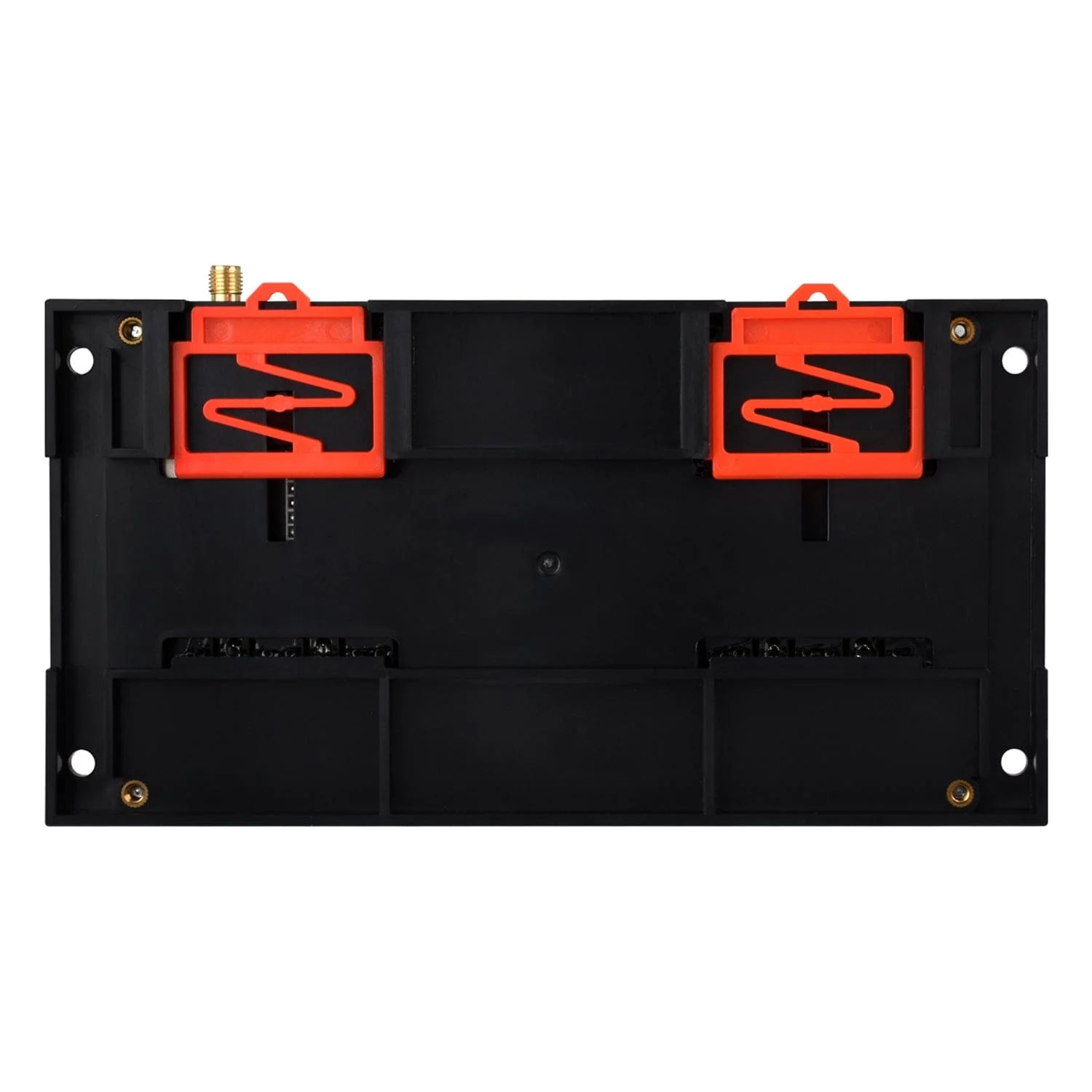
- Rail‑mounted ABS case for easy, safe installation
- Optional PoE version with built‑in IEEE 802.3af‑compliant module
Specifications
| Microcontroller | ESP32-S3 (ESP32-S3-WROOM-1U-N16R8) |
| Wireless communication | 2.4GHz Wi‑Fi (802.11 b/g/n), Bluetooth 5, BLE |
| USB connector | USB‑C |
| Power supply (USB) | 5V |
| USB functions | Power supply, USB communication, firmware downloading, etc. |
| Isolated communication interface | CAN |
| Connector | Screw terminal |
| Direction control | Hardware automatic control |
| Protection | TVS diode, surge protection & ESD protection |
| Resistor | Onboard reserved 120R matching resistor, NC by default, enabled via jumper |
| Ethernet interface | PoE Ethernet port, supports IEEE 802.3af standard (for PoE port version only) |
| Digital input channels | 8 |
| Digital input voltage | 5V~36V |
| Digital input type | Passive input / active input (NPN or PNP type) |
| Digital input isolation | Bi‑directional optocoupler isolation |
| Relay contact rating | ≤10A 250V AC / 30V DC |
| Relay channels | 8 |
| Relay contact form | 1NO 1NC |
| Relay isolation | Optocoupler isolation |
| RGB | RGB LED, supports programmable control of display colour |
| PWR | Red power indicator, lights up when there is a USB connection and voltage is detected |
| TXD | Green TX indicator, lights up when the CAN port sends data |
| RXD | Blue RX indicator, lights up when the device port sends data back |
| Power supply (screw terminal) | 7~36V |
| Enclosure | Rail-mount ABS protective case |
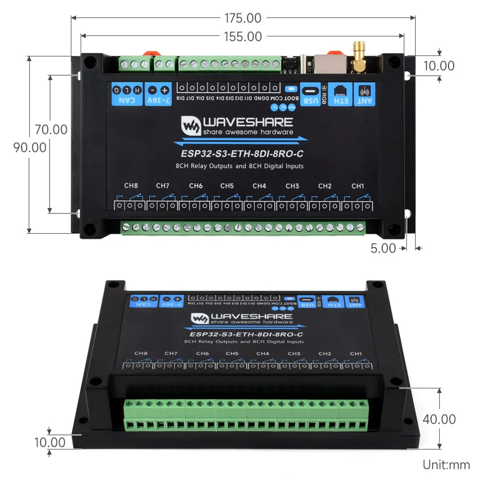
| Dimensions | 175 × 90 × 40 (mm) |
Resources
Package Contents
- 1x 8-Channel ESP32-S3 Wi-Fi Relay Module with CAN Interface (select version before adding to cart)
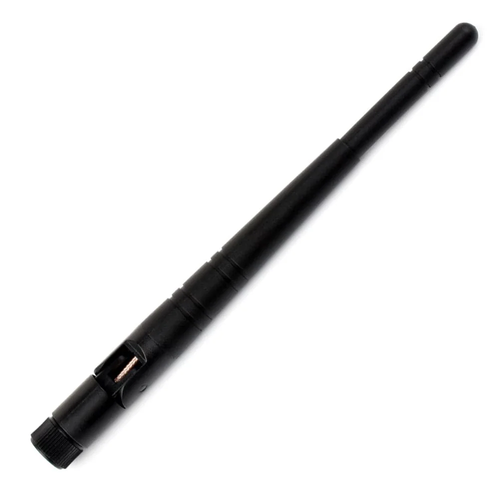
- 1x 2.4G 4DB SMA antenna
- 1x Screwdriver
Original: $43.20
-65%$43.20
$15.12Product Information
Product Information
Shipping & Returns
Shipping & Returns
Description
The Waveshare 8-Channel ESP32-S3 Wi-Fi Relay Module is based on an ESP32‑S3 microcontroller with an Xtensa 32‑bit LX7 dual‑core processor running up to 240 MHz, featuring 2.4 GHz Wi‑Fi and Bluetooth LE dual‑mode wireless, and adds a W5500 Ethernet chip over SPI for a 10/100 Mbps network port (with the option for PoE support).
I/O is set up for real‑world control: high‑quality relays (≤10 A at 250V AC / 30V DC), passive and active digital inputs with bi‑directional optocoupler isolation, and linkage so relays can follow digital inputs.
Optocouplers prevent interference from external high‑voltage circuits on the relay side, with digital isolation to keep external signals clean, and a unibody isolated power supply that provides a stable isolated voltage so the isolated terminal needs no extra supply.
An onboard isolated CAN interface connects to a range of CAN devices, and a pin header gives access to other peripherals. Power it via the USB‑C port (also used for firmware downloading and debugging) or the screw terminal with a wide 7–36 V input.
An onboard RTC supports scheduled tasks (with a CR1220 battery holder for rechargeable coin cells only), there’s a MicroSD card slot for storing images and files, and you get a built‑in buzzer, RGB LED, plus power and CAN TX/RX indicators to monitor device status. It’s all housed in a rail‑mounted ABS case that’s easy to install and safe to use.
There are two versions of this product available - one with a standard/common Ethernet port, and one with a PoE network port (via a built‑in IEEE 802.3af‑compliant module), please select an option before adding to your cart.
What's Onboard?
-
ESP32-S3-WROOM-1U-N16R8
- ESP32‑S3 series with Xtensa 32‑bit LX7 dual‑core processor, 16 MB Flash and 8 MB PSRAM.
-
8‑channel relays
- Contact rating per channel: ≤10 A at 250 V AC or 30 V DC.
-
Optocoupler isolation
- Prevents interference from external high‑voltage circuits connected to the relay.
- Reset button
-
PoE header
- Connects to a PoE module to add PoE capability (PoE‑port version only).
- Boot button
- Power IC
-
Digital isolation
- Prevents interference from external signals.
-
Power‑supply isolation
- Provides a stable isolated voltage; no extra power supply needed for the isolated terminal.
- Bi‑directional optocoupler isolation
-
RTC battery holder
- CR1220 size, supports only rechargeable 3.0–3.3 V batteries.
- Buzzer
- Digital input screw terminals
-
Pin header
- For connecting other devices.
-
LED indicators
- PWR: power indicator.
- RXD: CAN RX indicator.
- TXD: CAN TX indicator.
-
USB Type‑C connector
- Power supply, firmware download and USB communication.
-
WS2812 RGB LED
- Controllable via GPIO38.
- Ethernet port
-
External antenna connector
- SMA female for Wi‑Fi and Bluetooth.
-
Power‑supply screw terminal
- DC 7–36 V wide‑range input.
-
CAN interface
- Connects to external CAN devices.
-
CAN matching resistor jumper
- Onboard 120 Ω matching resistor; enable via jumper.
- Relay screw terminals
-
Onboard TVS (Transient Voltage Suppressor)
- Suppresses surge voltage and transient spikes in the circuit.
- CAN conversion chip
-
MP1605GTF‑Z
- DC‑DC power module.
-
PCF85063ATL
- RTC chip; supports scheduled tasks.
-
TCA9554PWR
- GPIO expansion chip.
-
W5500
- Adds a 10/100 Mbps network port via SPI.
-
MicroSD card slot
- Supports external MicroSD card storage for images and files.
Features
- ESP32‑S3 MCU (Xtensa 32‑bit LX7 dual‑core, up to 240 MHz)
- 2.4 GHz Wi‑Fi + Bluetooth LE (dual‑mode), superior RF performance
- High‑quality relay, contact rating ≤10 A @ 250 V AC / 30 V DC
- Passive/active digital inputs with bi‑directional optocoupler isolation; relay supports digital‑input linkage
- Isolated CAN interface for connecting to CAN devices
- Pin header for access to additional devices
- USB‑C for power, firmware download and debugging
- 7–36 V screw‑terminal power input
- RTC for scheduled tasks
- W5500 Ethernet over SPI for 10/100 Mbps network port
- Optocoupler isolation against interference from external high‑voltage circuits on the relay side
- Digital isolation to prevent external signal interference
- Unibody power‑supply isolation provides stable isolated voltage; no extra supply needed at the isolated terminal
- MicroSD card slot for image/file storage
- Built‑in buzzer, RGB LED, power and CAN TX/RX indicators for status monitoring
- Rail‑mounted ABS case for easy, safe installation
- Optional PoE version with built‑in IEEE 802.3af‑compliant module
Specifications
| Microcontroller | ESP32-S3 (ESP32-S3-WROOM-1U-N16R8) |
| Wireless communication | 2.4GHz Wi‑Fi (802.11 b/g/n), Bluetooth 5, BLE |
| USB connector | USB‑C |
| Power supply (USB) | 5V |
| USB functions | Power supply, USB communication, firmware downloading, etc. |
| Isolated communication interface | CAN |
| Connector | Screw terminal |
| Direction control | Hardware automatic control |
| Protection | TVS diode, surge protection & ESD protection |
| Resistor | Onboard reserved 120R matching resistor, NC by default, enabled via jumper |
| Ethernet interface | PoE Ethernet port, supports IEEE 802.3af standard (for PoE port version only) |
| Digital input channels | 8 |
| Digital input voltage | 5V~36V |
| Digital input type | Passive input / active input (NPN or PNP type) |
| Digital input isolation | Bi‑directional optocoupler isolation |
| Relay contact rating | ≤10A 250V AC / 30V DC |
| Relay channels | 8 |
| Relay contact form | 1NO 1NC |
| Relay isolation | Optocoupler isolation |
| RGB | RGB LED, supports programmable control of display colour |
| PWR | Red power indicator, lights up when there is a USB connection and voltage is detected |
| TXD | Green TX indicator, lights up when the CAN port sends data |
| RXD | Blue RX indicator, lights up when the device port sends data back |
| Power supply (screw terminal) | 7~36V |
| Enclosure | Rail-mount ABS protective case |
| Dimensions | 175 × 90 × 40 (mm) |
Resources
Package Contents
- 1x 8-Channel ESP32-S3 Wi-Fi Relay Module with CAN Interface (select version before adding to cart)
- 1x 2.4G 4DB SMA antenna
- 1x Screwdriver